Although thermocouples are the most commonly used temperature sensor in test applications, a close second is the resistance-temperature detector, or RTD. RTDs operate on the principle that the resistivity of a metal is proportional to its temperature. The higher the temperature, the higher the resistivity.
RTDs are generally made with platinum wire, although other types of wire are sometimes used for special applications. Platinum is most often used because it is chemically inert and has a temperature coefficient of resistance that is nearly linear and large enough to yield excellent temperature resolution. The temperature range over which you can use RTDs is -200°C to about +850°C.
RTDs are generally designed to have a nominal resistance of 100Ω at 0°C, although you can also purchase RTDs with nominal resistances ranging from 50Ω to 2000Ω. To calculate the resistance of an RTD, you need to know its resistance coefficient, or α, which is specified in Ω/Ω/°C.
You then use the equation Rt = Rn(1 + αt), where
- Rt = the resistance of the RTD at temperature t
- Rn = the nominal resistance of the RTD
- t = temperature for which the resistance is being computed in °C.
The most common value of α is 0.00385 Ω/Ω/°C, but the American Scientific Apparatus Makers Association’s RC21-4-1966 specifies an α of 0.003923, and the U.S. DOD’s MIL-T-24388 specifies an α of 0.00392. When ordering an RTD, you must specify both the alpha and resistance value at 0°C (Rn) to match the measuring instrumentation you will be using.
RTDs can be made using wirewound elements or film elements on a ceramic substrate that are then encased in ceramic. RTDs are available in two-wire, three-wire, and four-wire configurations. The two-wire configurations are the least accurate. The reason for this is that the resistance of the leads connecting the RTD to the measuring instrument cannot be compensated for, leading to inaccuracies. Four-wire RTDs are the most accurate because you can make a four-wire resistance measurement that completely compensates for the lead resistance. The disadvantage is that using four-wire RTDs requires more cabling and allows fewer RTDs to be connected to an instrument.
That leaves three-wire RTDs. Three-wire RTDs are the most commonly used RTDs for industrial and test applications. Using three-wire RTDs reduces the amount of cabling needed but provides more accuracy than two-wire RTDs. Three wire RTDs normally use a Wheatstone bridge measurement circuit, as shown below, to measure the resistance of an RTD.
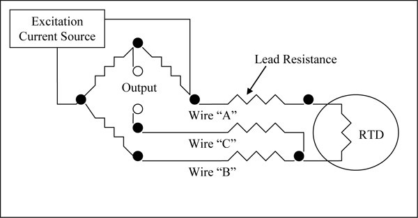
In this configuration, wires “A” and “B” should be close to the same length so that their resistances don’t have an appreciable effect on the measurement. Wire “C” is the sense lead, and since it carries only microamperes of current, its resistance has only a very small effect on the measurement.
The VTI Instruments EX10XX family of instruments can be used to measure temperature with RTDs. It can make either three-wire or four-wire measurements from -2000°C to +850°C. With a 100Ω, platinum RTD, the temperature accuracy is ±0.45°C.
For more information on RTDs and how to use them in your test system, contact one of our sales representative by visiting https://www.vtiinstruments.com/sales/vti-instrument-sales. You can also email us at sales.ppd@ametek.com or call 800-733-5427 or 858-450-0085.